Engine:
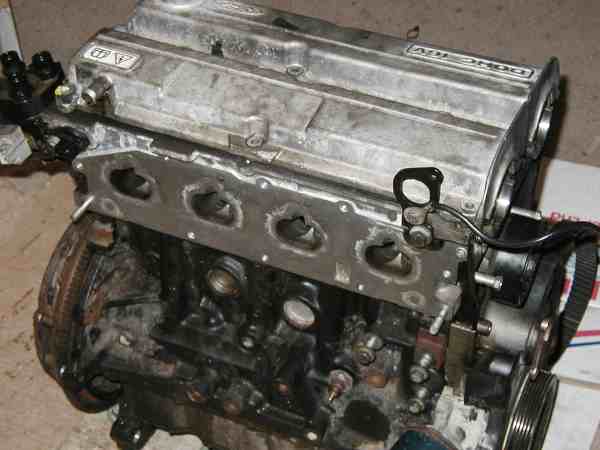
The engine started life in a 1.8 Ghia Si Escort, we chose 1.8 as it was easily available and cheap. To fit a 2.0 block requires the sump/oil pickup and flywheel/clutch at least (maybe oil pump too) from a 1.8 to allow it to fit the MK3 gearbox and exhaust. All round easier to just use a 1.8 block - we weren't out for monster power here.
here it is pulled from the breakers:
A few parts have been stripped off by now, needed a good clean to see what we'd got.
A number of issues need addressing from the outset:
1, Compression ratio reduction
2, Exhaust manifold fitment
3, Injector and fuel rail fitment
4, Block breathers and turbo oil return
5, Crank and cam sensor fitment
6, Coolant and Inlet air temperature sensor fitment
7, Right hand engine mount modification to clear oil pump
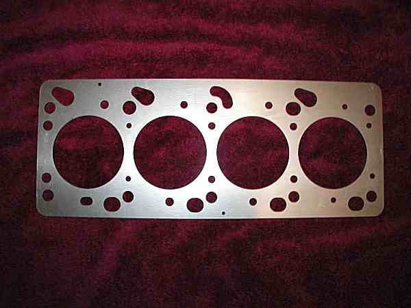
Decompression Plate:
In the interest of the weight of the wallet, compression ratio was going to be dealt with by using a decompression plate - the 'proper' way is obviously to use forged pistons with a suitable compression height, but at £4-500 a set that wasn't an option until we'd proved the plate wouldn't work. We'd got a plan for the plate anyway, so there's a good chance it would be OK...
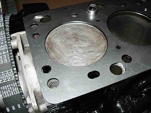
The plan was to seal the laser cut steel plate to the top of the block, firmly located on the head-alignment dowels. A single normal head gasket would seal the plate to the head. This way the plate would expand with the block whilst unable to move around freely due to the dowels, and the head and head gasket would be able to move and function as intended - using a gasket both sides of the plate was going to be asking for trouble.
The plate thickness was calculated to be 2.5mm for a 8.2:1 CR, was drawn up on CAD by ourselves (using a gasket as a guide) and manufactured by a local engineering firm for a very reasonable price. Much attention was given to ensuring that the main bore diameters were such that we the gasket was seating entirely on the plate with no risk of overhang into the bore, whilst also ensuring clearance for the pistons, as they protrude from the block about 0.5mm at TDC.
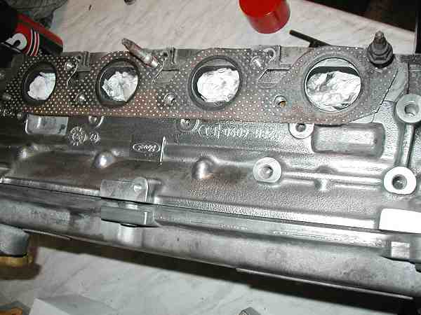
Exhaust manifold:
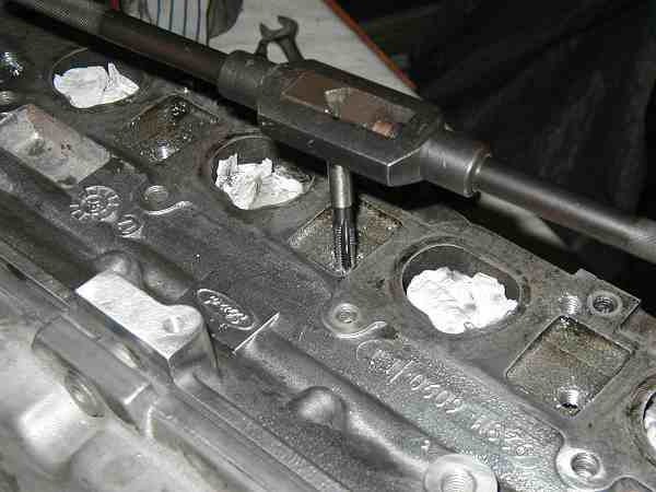
The exhaust manifold used is the standard Escort Turbo item with T3 turbo attached. The port centres are the same on Zetec and CVH engines which is handy, but the studs are in completely the wrong positions - all 8 need to be redrilled and tapped in the correct position. A new exhaust gasket is used as a template to mark out the new hole positions, then carefully drilled and tapped using a simple pillar drill.
It's worth noting that the top row at least, all break into the oil return channels, so care is needed to make sure the drill doesn't snag, and obviously there's a lot of swarf to clean out afterwards!
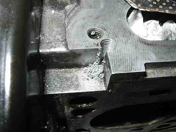
The lower front hole actually breaks out of the casting as shown below.. ideally the corner would be filled with weld first and a full hole tapped, but in practice the thread is strong enough if carefully tapped.
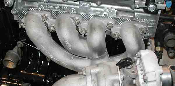
Exhaust manifold bolted in position..
Injectors and Fuel Rail:
To fit the cosworth injectors into the Zetec inlet manifold, a few modifications are needed..
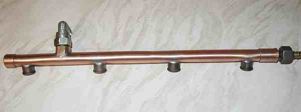
A custom rail has to be fabricated to start - we did this using copper pipe and injector connector stubs salvaged from another rail.
.
The original injector mounting casting is modified to remove excess unnecessary metal where the original fuel pipe connections and regulator attach - the injectors fitted into the pockets nicely, with the o-rings sealing correctly at the bottom. A thin o-ring is fitted to the top of the body to hold it snugly in the casting.
The finished rail
with suitable mounting brackets attached came out like this.... 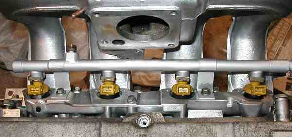
Block Breathers and Turbo Oil Return.
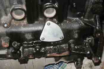
The main Zetec breather assembly mounts on the front of the block, and completely interferes with the exhaust manifold and turbo, so needs to be removed and blanked off with a plate:
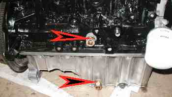
To compensate additional breather port is drilled into the back of the block, with an oil return fitting in the sump. A similar fitting is positioned in the front of the sump to accommodate oil return from the turbo. The existing breather port on the cam cover is also available to breath from.
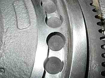
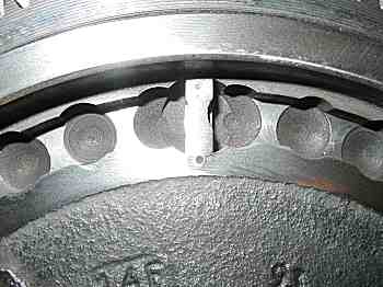
Crank and Cam Sensor fitment:
The Marelli management requires a crank sensor signal with four pulses per rev. at TDC, 90deg, 180 deg. and 270deg. This is accommodated by modifying the standard Zetec flywheel sensor teeth, machining off what isn't needed, just leaving behind four teeth in the correct position. Unfortunately one of those positions is occupied by the 'missing tooth' on the zetec flywheel, so a piece of steel had to be fabricated and let in to fill the position. The standard Zetec crank sensor is retained.
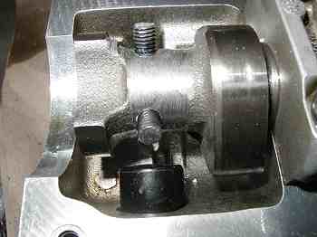
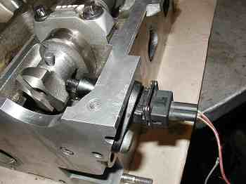
The system also needs emulation of the phase sensor which is normally in the distributor - no distributor on Zetec, so this is a bit more tricky... A bit of jiggery-pokery on the back end of the inlet cam (where the Zetec cam sensor normally resides) see's the existing single lobe ground off the cam and two pegs let into the cam in the correct position to represent the phase sensor - a bit more about this in Management section.
Coolant and Inlet Air Temperature sensors:
The positions of both these sensors is retained in the original Zetec positions, coolant in the top of the thermostat housing and inlet air temp. in the back of the inlet manifold opposite the throttle housing.
The threads of these two sensors is different, so adaptor sleeves need to be made to fit the sensors in the BSP threaded ports of the Zetec - M14x1.25mm for the inlet air sensor and M12x1.25mm for the coolant sensor.
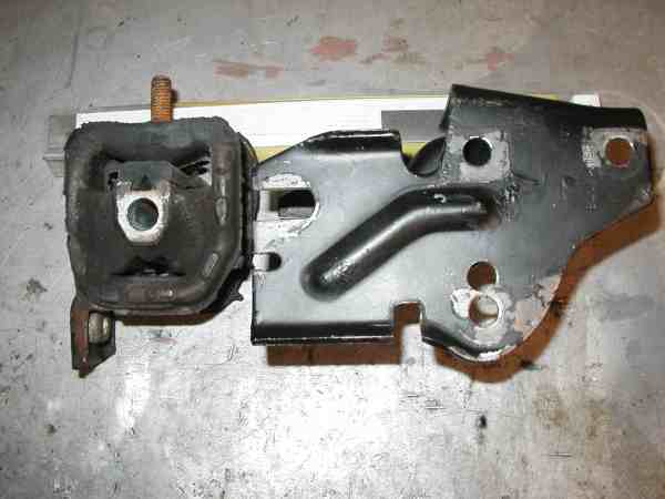
Right Hand Engine Mount:
The right hand engine mount from the CVH engine is easily adapted to fit the zetec block and mate up with the MK3 chassis mount. By accident we discovered that there is an optimum combination of engine mount components from different age vehicles which minimises the amount of cutting required on the engine bracket.
Fundamentally the engine bracket needs to be cut so it doesn't foul the oil pump, it's fairly obvious what's needed when you offer it up. one of the lower fixing holes is in a different position, but in practice the two fixings which do align are more than adequate for the job. By selecting the right parts though, it's easy to redrill the third hole.
The chassis mounting rubber portion of the mount is always the same - early MK3, part number 81AB6038AC, the engine bracket is best sourced from late MK3 or early MK4, part number 84AB6A060BB. This combination requires the least amount of cutting. The earlier engine bracket can be used, but is much stouter in all the wrong places, and will give your angle grinder a harder time.
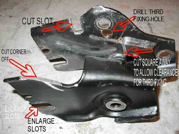
Engine mount 84AB6A060BB showing areas of modification:
Modified engine mount 84AB6A060BB, and chassis mount 81AB6038AC: