STILL UNDER CONSTRUCTION...
Electronic Management System:
A brief overview of the Cosworth Marelli management system will simplify understanding what we have needed to do here:
The following diagram gives a simple representation of the sensors and actuators, and their relationship with the engine -
We chose to
use a 4x4 Level 8 setup, mainly as we had a 4x4 Sapphire which we could use to
get a full understanding of how the system works in detail, to make it easier to
determine what we needed to do to incorporate the variations needed for our
installation.. The parts are available fairly cheaply if you search around. We
also already had a good known Stage1 chip for this ECU ![]()
There are some other useful pages, written by Willeon Peters in Holland, to look through, which relate to electrical testing for this system here , and more relating to the fault codes that may be stored in the ECU and how to retreive them here .
Essentially the same setup as the diagram above is incorporated into the Zetec installation, with a few notable diversions:
1, RPM/TDC sensor isn't on the front pulley, but in our case part of the flywheel
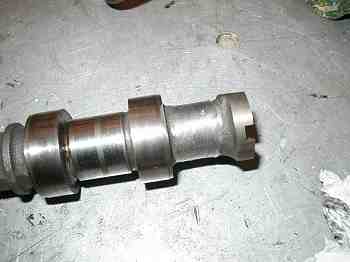
2, Phase sensor is not mounted in the distributor (there isn't one!), but on the back of the inlet cam
3, It isn't possible to mount the Marelli Throttle Position Sensor (TPS) on the Zetec throttle body, as the spindle rotates in the opposite direction, so the standard Zetec item is used. However, the voltage output characteristic isn't the same, so an in-line electronic conditioning circuit is incorporated between the Zetec sensor and ECU to expand the output voltage span and emulate the signal range of the Marelli sensor. The Marelli Level 8 system we discovered, is quite heavily dependent on the TPS signal for proper running, especially at light throttle, so this is a significant requirement.
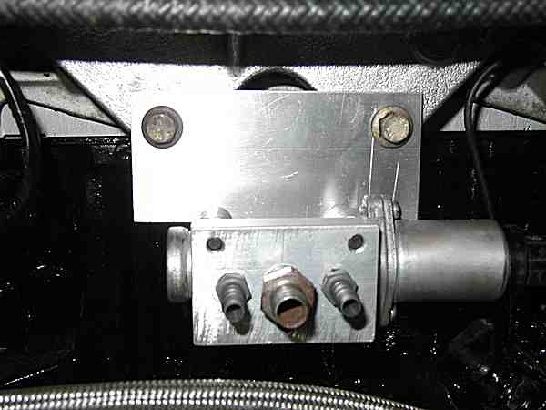
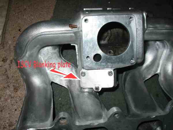
4, The Idle Speed Control Valve (ISCV) mounts into the throttle body on the Marelli setup, on the Zetec installation we used the Zetec ISCV on a custom made bracket and air manifold, mounted behind the engine and plumbed from the charge carrier crossover pipe to the back of the inlet manifold. A blanking plate masked the original position below the throttle body:..
Alternatively, a remote holder for the Marelli valve is available from Weber-Webcon, which would be a better solution, as the proper valve is better matched to the ECU drive signal.
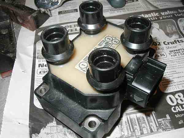
5, Perhaps most significantly, the conventional ignition coil in the Marelli system is driven from a single amplifier module, triggered by signals from the ECU, and the spark routed through the distributor. The Zetec of course doesn't have a distributor, so a mechanism is required to fire the twin-coil pack on the Zetec using a pair of amplifier modules. Looking at the wiring diagram, it is evident that two sets of signals come from the ECU to a pair of amplifiers - inside the ECU there is microprocessor controlled module which we developed to perform this task, more of this later..
Other than this, standard Marelli parts were used - 2-bar MAP sensor, yellow injectors, coolant and inlet air temperature sensors, AMAL valve, standard S1 fuel pump and filter, and a pair of ignition modules.
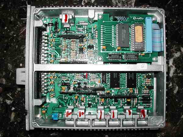
Here's a standard Marelli Cosworth 4x4 Level 8 ECU internal view - immediately after we attacked the unmolested mint ECU, broke the intact screw seals and took the lid off!
Distributorless ignition dual-amplifier driver module:
The Marelli L8 ECU takes in signals from the TDC/RPM sensor, and Phase Senor, and generates a pulse train of ignition trigger signals which drive the external ignition amplifier, which in turn switches the coil.
We had to develop a system that would take this ignition trigger pulse train and route alternate pulses to a pair of amplifiers, which in turn switch the dual coil pack , at the right time, in the right sequence! This was probably the trickiest part of this conversion to get our head round, and thanks must go to our friend Colin for his assistance with the software.
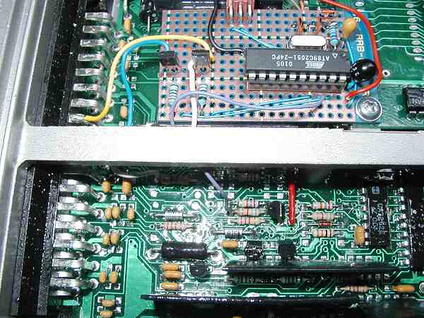
We designed a microprocessor based interface to do this, picking up TTL level conditioned TDC and Phase sensor signals from inside the ECU, and the ignition trigger signal, then outputting two individual trigger signals for the two amplifiers. The interface is mounted inside the ECU out of harms way, and spare pins on the ECU used to take the two signals out (ECU pin 9 and 26 on the wiring diagram, they don't connect to anything inside the ECU).
Another view inside the ECU with DIS interface fitted..:
The ignition firing point remains unaltered in this process, and remains under full control of the ECU map - the module purely routes each ignition pulse to the correct amplifier/coil/cylinder at the correct time.
As with the standard setup on Cosworth cars, the grounding arrangement is of paramount importance if amplifier interference and misfire is to be avoided. The wiring from the coil to amplifier, and amplifier ground connection to chassis must be as short and direct as possible, otherwise there is a good risk of getting volt drops her, and strange signals introduced into the amplifier inputs due to the high coil switching currents; this causes loopy tacho activity, inconsistent coil energy and ultimately misfires.
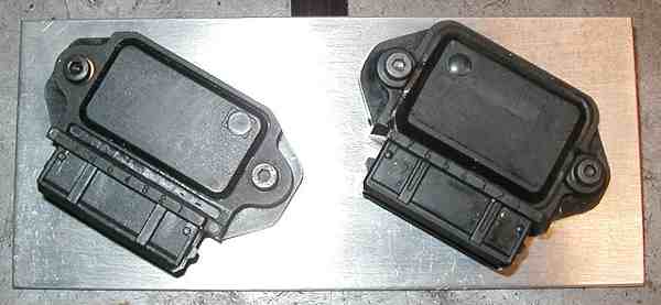
Twin ignition amplifiers mounted on heatsink plate:
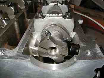
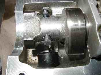
Phase Sensor:
The Cosworth phase sensor
is usually mounted inside the distributor. As the Zetec is distributorless, a
mechanism is required that emulates this signal. Zetec has a cam sensor as
standard, but is in the wrong position with respect to crank angle - so we
ground off the cam sensor lobe from the back of the inlet cam, then marked and
drilled the cam to take two pegs which would trigger the standard Zetec sensor
which mounts in the side of the head. The pegs have to be in the correct
position with respect to crank position also, so some careful timing
measurements and marking out is required! We didn't want to be scrapping too
many cams getting it right ![]()
Cam sensor lobe ground off: view of cam sensor and pegs:
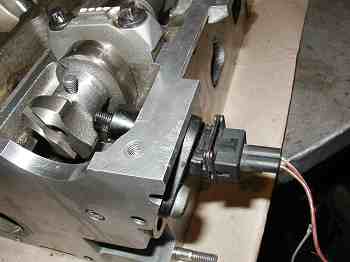
End view of pegs: Close-up of pegs:
Coolant and Inlet Air Temperature sensors:
The positions of both these sensors is retained in the original Zetec positions, coolant in the top of the thermostat housing and inlet air temp. in the back of the inlet manifold opposite the throttle housing.
The threads of these two sensors is different, so adaptor sleeves need to be made to fit the sensors in the BSP threaded ports of the Zetec - M14x1.25mm for the inlet air sensor and M12x1.25mm for the coolant sensor.
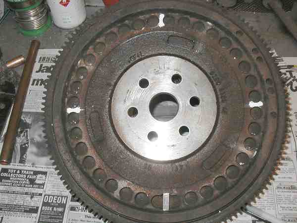
Flywheel modification for TDC sensor
As mentioned in the Engine section, the 4-peg TDC/RPM ring and sensor, which is normally part of the Cosworth front pulley, was emulated by modifying the Zetec flywheel to machine away the unwanted teeth, leaving just the ones at 90, 180, and 270 degrees. there is a gap at 0 deg. (TDC) so a piece of steel needs to be let in to form the forth tooth. This was made a very tight 'bash' fit and staked in position as seen in the pics..
Flywheel marked up ready for machining.. (white teeth to remain)
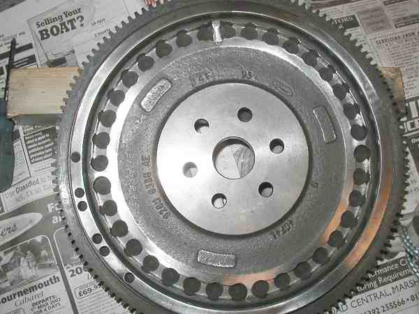
Flywheel after machining - and cleaning!
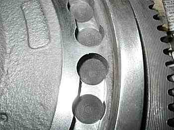
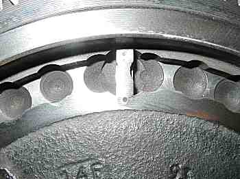
close-up of remaining tooth. new tooth let into original gap.